Introduction
This section describes the software user interface and the functionality that it provides.
Toolbar icons
An installation of CIMCO Edit Verify automatically adds the icons to the Mastercam toolbar.
![]()
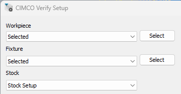
Setup
Setup allows you to determine which geometry and whether machine simulation will be used within CIMCO Edit Verify prior to launch.
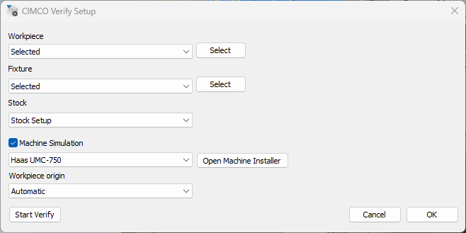
Workpiece, Fixture and Stock
Under Workpiece, Fixture and Stock, from the dropdown menu, choose the option for how the geometry should be selected.
None = No geometry will be selected
Selected = Select geometry from the Mastercam window
External STL = Select geometry from an external folder
From level = Select the geometry from a level
Stock Setup = Use the stock setup within Mastercam
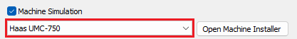
Machine Simulation
Determines whether CIMCO Edit Verify will load a Machine on launch.
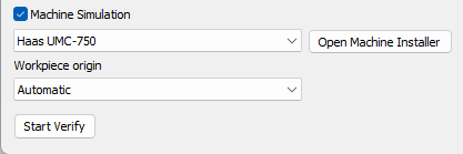
Use the check box beside Machine Simulation to indicate whether Machine Simulation will be used or not.

Checked = Machine Simulation will be used at launch. (can still be toggled on/off within CIMCO Edit Verify as the machine is already loaded)
Use the Open Machine Installer to access available machines and download them from the machine server. The machines available to download depends on which machines have been included on a user CIMCO Edit Verify license.
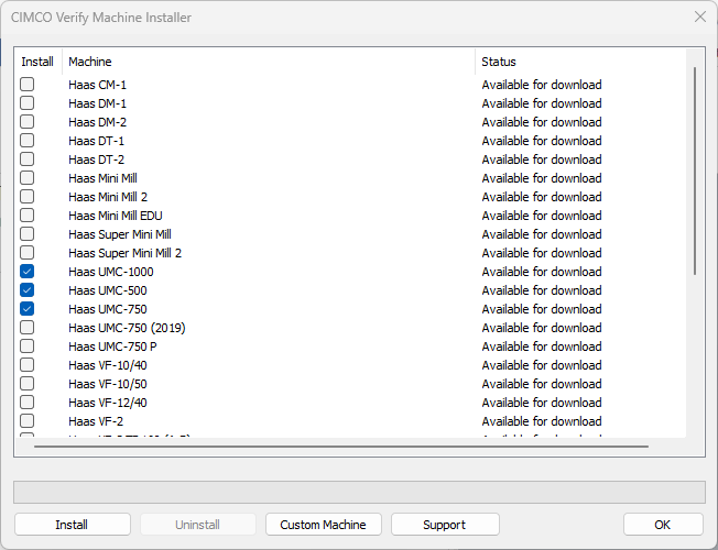
Install = Select the machines you wish to install. Select the install option to begin downloading the machine. After the machine has been downloaded it will become available through the machine selection drop down menu.
Uninstall = Select this option to uninstall a machine.
Custom Machine = Select this option to import a .CimcoSimBundle. A .CimcoSimBundle will be provided to a user who has requested a custom machine build from CIMCO. If a specific machine is not available on the server, a custom build will need to be used. Please contact [email protected] for further information.
Support = Select this option for further information on how to contact support.
Workpiece Origin
Determine the origin within Mastercam to be used as the zero position on the machine table.
Automatic = Uses World and takes the lowest point of fixture/workpiece and stock
World = Select this option to use the World origin
WCS = Select this option to use the WCS origin
Selected = Select this option to manually select the origin
User Interface
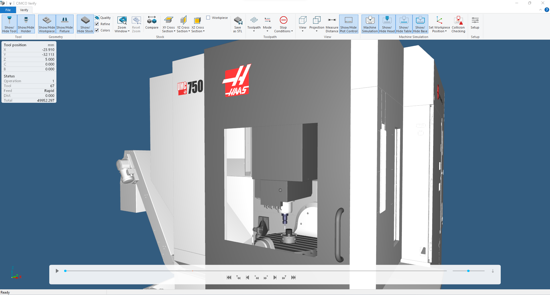
Launch CIMCO Edit Verify to utilise the powerful advancements CIMCO Edit Verify’s Backplotter, Stock and Machine Simulation add-in.
Taskbar
The taskbar contains many functions and features from toolpath animations to Stop Conditions.

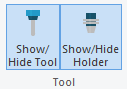
Tool
Show/Hide Tool = Select this option to toggle between showing and hiding the tool. Show/Hide Holder = Select this option to toggle between showing and hiding the holder.
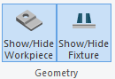
Geometry
Show/Hide Workpiece = Select this option to toggle between showing and hiding the workpiece. Show/Hide Fixture = Select this option to toggle between showing and hiding the fixture.
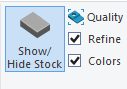
Stock
Show/Hide Stock = Toggle between showing and hiding the stock. Quality = Determine the quality of the stock. The quality of stock chosen will alter the speed/performance of Verify. Refine = Enable stock refine. Colours = Enable a unique colour by tool.
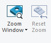
Zoom Window = Increase the accuracy of the stock by creating a cut out of the stock that covers the window. Zoom Selection = Increase the accuracy of the stock by creating a cut out of the stock that covers a user’s selection. Reset Zoom = Reset the cut out of the stock to the original stock.
Compare = Compare the simulated stock to the design model. The stock is coloured on the distance to the design model to easily identify any inaccuracies, whether too much stock has been removed (the tool gauges the design model) or where not enough stock has been machined.

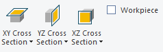
XY Cross Section = Cross section view of current stock in XY plane.
- Z+ = Cross section view by Z+ plane
- Z- = Cross section view by Z- plane
- Off = Disable cross section
YZ Cross Section = Cross section view of current stock in YZ plane.
- X+ = Cross section view by X+ plane
- X- = Cross section view by X- plane
- Off = Disable cross section
XZ Cross Section = Cross section view of current stock in XZ plane.
- Y+ = Cross section view by Y+ plane
- Y- = Cross section view by Y- plane
- Off = Disable cross section
Workpiece = Check this item to apply the cross section view to workpiece as well as the simulated stock. When checked, the stock can be easily compared to the workpiece on the cross section plane.
Save as STL = Save and export the stock in its current form as an STL file.

Toolpath
Toolpath = Toggle toolpath view settings.
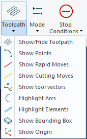
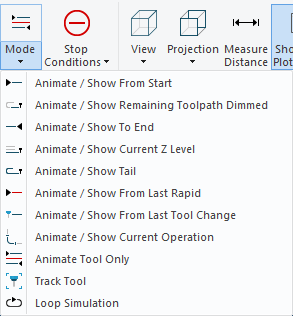
Mode = Toggle toolpath mode animations.
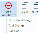
Stop Conditions = Toggle Stop Conditions. Stop the simulation process at user specific trigger events.
View
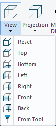
View = Select the view in which the simulation contents will be displayed.
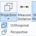
Projection = Select the projection view in which the simulation contents will be displayed.
-
Perspective = Renders the scene using a camera position and a field of view. This projection is in perspective view, the camera can move through geometries which is useful to bring it inside the holes or similar places when inspecting fine details. It is even possible to bring the camera inside the tool which is useful to see the exact overlap with geometries during collisions. However, geometries far away appears smaller on the screen, making it harder to compare the relative size of objects.
-
Orthographic = Projects the scene onto the screen while preserving the relative size of the geometries. This makes it easier to compare the geometries at different depths. The camera position is always far away from the scene, it cannot be freely positioned.
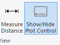
Measure Distance = Measure the distance between any two points on a toolpath and geometries.
Show/Hide Plot Control = Show/Hide the simulation plot control bar.
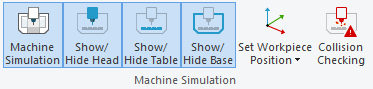
Machine Simulation
Machine Simulation will detect machine collisions and limit errors. Toggle between Verify and Machine Simulation without having to restart CIMCO Edit Verify.
Machine Simulation = Enable/Disable the Machine Simulation mode
Show/Hide Head = Show/Hide the machine head components
Show/Hide Table = Show/Hide the machine table components
Show/Hide Base = Show/Hide the machine base components
Set Workpiece Position = Select this option to manually define the workpiece position
Reset to default = Reset workpiece position to default
Collision Checking = Show machine collisions and limit errors
After selecting Collision Checking, a Collision Checking Dialog will open. This dialog reports any collisions and limit errors found within the program.
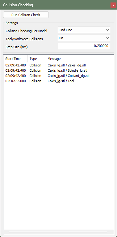
Run Collision Check = Starts the collision checking process. Any collisions or limit errors found will be reported in the dialog below. Collisions will be reported with the following information:
- Start Time = The time in which the collision occurs
- Type = Whether it is a collision or limit error
- Message = Outlines what specific components are colliding, and which specific machine components are exceeding their travel limit
- Collision checking per model = Find one will report a collision if found (faster). Find All will report all collisions if found (slower)
- Tool/Workpiece Collisions = Toggle whether collisions between the tool and workpiece are reported
- Step size = Set the distance with which the toolpath is sampled when collision checking
Setup
Setup = Update setup. This will open the CIMCO Edit Verify Setup dialog.
